
Understanding Insulator Failure Modes in Modern Switchgear
Forensic review of failed switchgear components consistently points to three interrelated failure mechanisms: surface tracking, flashover, and mechanical fracture. Each originates from a distinct physical stressor, yet all three converge on the same structural element — the insulating standoff or busbar support that separates current-carrying conductors from grounded enclosures. Understanding these mechanisms is the starting point for selecting insulation systems engineered to resist them.
Tracking and Surface Carbonization
Surface tracking begins when contamination, humidity, or dust forms a conductive film across an insulator’s surface. Under sustained voltage stress, this film carbonizes incrementally, etching a permanent conductive path into the material. In high-voltage DC solar and battery systems, this risk is amplified because DC arcing lacks a natural zero-crossing point — unlike AC systems, there is no periodic moment where current drops to zero and interrupts the arcing process. The result is continuous surface tracking risk rather than a self-limiting event.
Flashover Under Transient Overvoltage
Flashover occurs when a transient overvoltage event — a switching surge or lightning-induced impulse — exceeds the dielectric withstand capability of the insulating gap. Enclosed switchgear compounds this risk: non-compliant plastics can ignite during internal arc faults, turning a localized electrical event into a sustained fire hazard within the cabinet.
Mechanical Fracture from Thermal Cycling and Short-Circuit Forces
Mechanical fracture is often the least discussed but equally consequential failure mode. Short-circuit events generate electrodynamic forces that place direct mechanical stress on busbar supports. Separately, repeated thermal cycling causes differential expansion between copper or aluminum busbars and the composite supports holding them, introducing cumulative micro-stress at the interface over the equipment’s service life.
Material Science Behind Failure Prevention
CTI and Material Group Classification
The Comparative Tracking Index (CTI) quantifies a material’s resistance to conductive carbon tracking. Insulation rated at a CTI of 600V or higher falls into Material Group I, the classification associated with the strongest resistance to tracking failure. This metric is particularly relevant for Pollution Degree 3 industrial environments, where airborne contaminants accelerate surface conductivity formation.
Flame Retardancy and Self-Extinguishing Behavior
UL 94-V0 certification addresses the flashover-to-fire escalation pathway. A V0 rating requires that afterflame time, measured as t1 + t2, does not exceed 8 seconds, with zero flaming drips — a critical specification for enclosed switchgear where molten, burning material could propagate a fault to adjacent compartments.
Thermal Expansion Matching
Mechanical fracture from thermal cycling is mitigated by matching the Coefficient of Thermal Expansion (CTE) of the insulating material to the conductors it supports. A CTE range of 15–22 × 10⁻⁶ /K aligns with copper’s 16.5 × 10⁻⁶ /K and aluminum’s 23.1 × 10⁻⁶ /K, reducing the differential stress that otherwise accumulates at the busbar-to-support interface across repeated temperature cycles. Operating temperature endurance from -40°C to +140°C further addresses the thermal loading seen in new energy applications such as battery containers.
Engineering Solutions from DOWE Electric
Yueqing City Duwai Electric Co., Ltd., operating under the DOWE Electric brand (also referenced as DUWAI), engineers insulation systems specifically against these three failure pathways rather than treating dielectric, thermal, and mechanical performance as separate design problems.
Low-Voltage Standoff Insulators
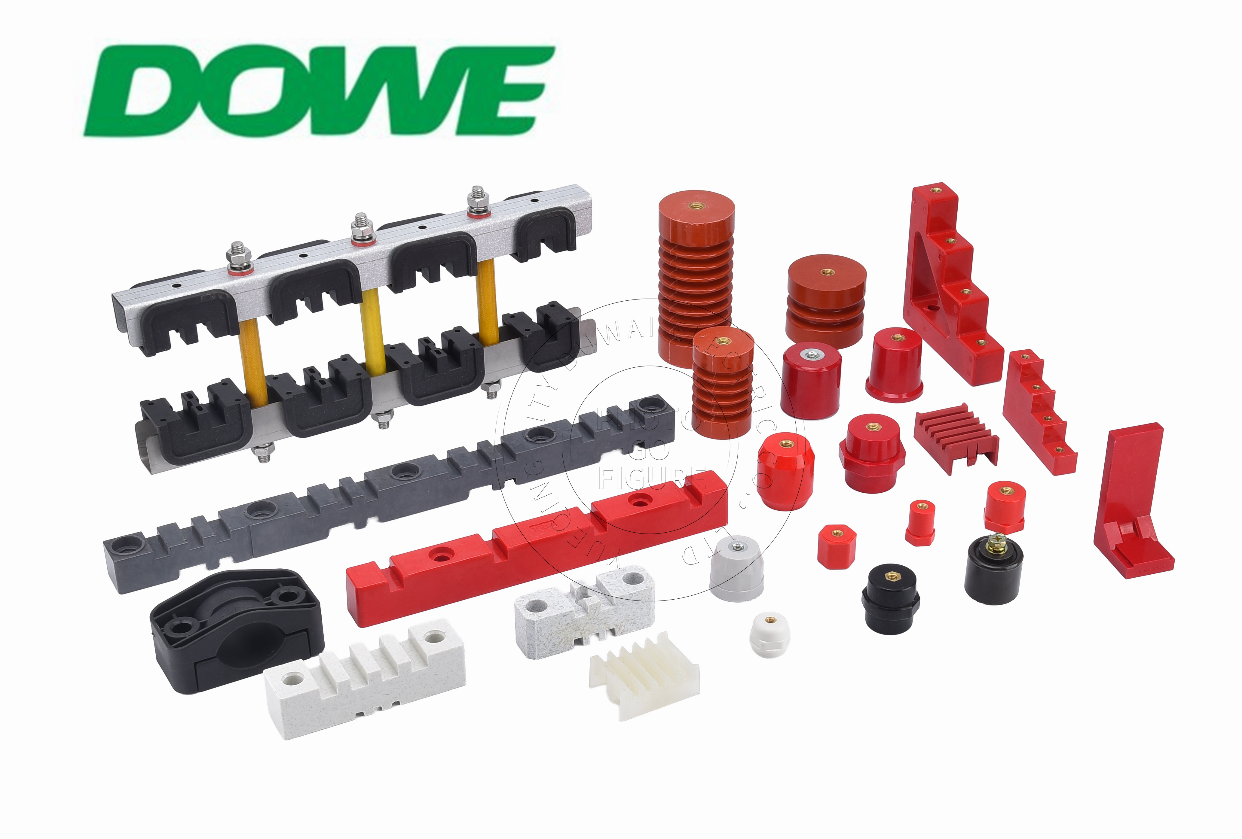
The SM Series uses a conical ribbed profile where concentric aerodynamic fins increase effective surface creepage path by 35% to 60% without increasing vertical installation height — a direct countermeasure against tracking in standard low-voltage switchgear, distribution panelboards, and motor control center cabinets. Constructed from high-grade BMC with a CTI of 600V or higher, the design limits the carbonized paths that lead to eventual flashover. Complementary lines — including the SEP Series for high-vibration industrial machinery and mining power boxes, the CT/CJ Series for layered multi-phase busbar arrangements, the D/C/EN Series for European-style panels and railway trackside power, and the TSM/MG Series for compact relay boards and smart meter boxes — extend this tracking-resistant approach across varied enclosure geometries. The MNS Series offers 1:1 drop-in OEM matching for ABB MNS 2.0/3.0 drawer-type cabinets, addressing legacy equipment replacement without panel redesign.
SB/JYZ Series for High-Voltage DC Applications
The SB/JYZ Series targets high-voltage DC environments up to 1,500V DC — solar PV, battery energy storage, EV charging, and DC fuse applications — where the absence of a zero-current crossing makes tracking especially destructive. Its hexagonal anti-rotation base allows assembly technicians to hold the base with an open-end wrench while applying full tightening torque, preventing rotational shear stress on the mounting plate during installation. With thermal endurance from -40°C to +140°C and UL 94-V0 self-extinguishing performance, the series addresses NFPA 855 BESS fire safety considerations. Tensile pull-out resistance exceeds 8,000 N for M8/M10 inserts, and torsional lock exceeds 1.5 times the bolt proof torque, directly countering the vibration-driven mechanical fracture risk seen in battery racks and lithium containers. The series spans dimensional models from SB14 through SB60, scaling body diameter, thread size, and material reinforcement (DMC/BMC through heavy-duty SMC) to match load requirements from compact power electronics up to utility-scale structural applications.
Busbar Support and Clamping Systems for Short-Circuit Withstand
Electrodynamic short-circuit forces are addressed by the busbar support and clamping product line, rated up to 1,100V AC and 6,300A. The EL Series provides pre-molded spacing (EL-130, EL-170, EL-210) in high-strength SMC, matching original mounting hole centers, busbar slot spacing, and creepage dimensions for ABB MNS, Schneider Blokset, and Siemens Sivacon platforms without panel redesign. For utility substations and high-current installations, the HC Heavy Duty line withstands short-circuit currents up to 100kA for 1 second (Icw), while the XD3-D4 Series accommodates variable busbar bar-counts from 1 to 3 bars per phase through modular interlocking design.
Medium-Voltage Insulators for Partial Discharge Control
At the medium-voltage tier, the DW Series serves 3.6 kV to 12 kV AC indoor switchgear and secondary distribution substations using DMC/BMC/SMC composite insulation. The EL MV Series, built from vacuum-cast epoxy resin via automated pressure gelation, targets 3.6 kV to 7.2 kV AC environments including ring main units and VFD drive cabinets. Its void-free monolithic casting controls internal partial discharge to less than 5 pC at 1.1 Um, while volume resistivity greater than 10¹⁴ Ω·cm and a dielectric loss angle (tan δ) no greater than 0.005 at 20°C maintain insulation integrity under extreme condensation.
Compliance and Verification Pathways
Forensic conclusions carry more weight when backed by third-party verification. DOWE Electric’s insulation systems are supported by SGS third-party type test reports, enabling panel builders to complete Design Verification documentation referenced against IEC 61439-1/2, IEC 60664-1, IEC 60273, IEC 60071, and IEC 60815, alongside UL 94-V0 flammability certification, UL 746B Relative Thermal Index certification, RoHS 2011/65/EU and 2015/863 compliance, REACH (EC 1907/2006) compliance, and CE clearance.
Practical Considerations for Panel Builders and EPC Contractors
For electrical panel builders, switchgear OEMs, and turnkey EPC contractors conducting failure analysis or specifying replacement components, the distinction between tracking, flashover, and mechanical fracture matters because each demands a different material response: CTI and creepage geometry for tracking, dielectric withstand and surge impulse margin for flashover, and CTE matching, tensile pull-out resistance, and torsional lock for mechanical fracture. Insulation systems that address all three simultaneously — as documented across the SM, SB/JYZ, EL, HC Heavy Duty, DW, and EL MV product lines — reduce the likelihood that a single unaddressed failure mode becomes the root cause of the next field incident.
http://www.busbarinsulator.com
Yueqing City DUWAI Electric Co.,LTD