
Understanding the Soldering Challenge for Header Pin Connectors
Header pin connectors are among the most widely used board-to-board and board-to-wire connection components in electronics, electrical appliances, and measurement equipment. Whether assembling a simple circuit board or building a high-density industrial control panel, engineers and technicians frequently ask how to solder header pins correctly to ensure a stable, long-lasting electrical connection. The process appears straightforward, but several environmental and mechanical factors—including high temperature during wave soldering, physical vibration, and long-term thermal cycling—can compromise the reliability of a soldered joint if the wrong connector or technique is used.
This article explains the practical soldering process for header pin connectors, the material and design factors that influence solder joint durability, and how connector manufacturers such as TXGA address these pain points through material engineering and quality testing.
Preparing for the Soldering Process
Before soldering header pins onto a printed circuit board (PCB), several preparatory steps matter:
- Pin alignment: Header pins must be inserted straight and fully seated into the PCB through-holes to avoid cold joints or mechanical stress after soldering.
- Pitch verification: Confirming the pin pitch (common options include 0.8mm, 1.0mm, 1.27mm, 2.0mm, and 2.54mm) against the PCB footprint prevents misalignment during reflow or wave soldering.
- Flux application: Applying flux to the pad and pin junction improves wetting and reduces oxidation during the heating process.
- Fixture use: For multi-row or high-density headers, a holding fixture or jig keeps pins perpendicular to the board during the soldering cycle.
Step-by-Step Soldering Technique
- Heat the joint, not just the solder: Position the soldering iron tip against both the pin and the PCB pad simultaneously so heat transfers evenly to both surfaces.
- Apply solder to the joint, not the iron: Feed solder wire directly onto the heated joint rather than melting it on the iron tip, which produces a stronger metallurgical bond.
- Control dwell time: Excessive heat exposure can degrade a connector’s insulating resin or plastic housing, particularly in headers not rated for high-temperature processes such as wave soldering.
- Inspect the joint: A properly soldered joint should appear shiny, with a smooth concave fillet connecting the pin to the pad—free from cracks, voids, or excess solder bridging.
- Clean residual flux: Removing flux residue after soldering helps prevent long-term corrosion or insulation resistance degradation.
Why Connector Material Selection Matters
One of the most overlooked factors in soldering success is the header connector’s base material. Many failures attributed to "bad soldering" are actually caused by connector housings that deform or degrade under process heat. TXGA’s 2.54mm Pin Header & Female Connector series was specifically engineered to address this pain point: high-temperature wave soldering deformation and signal interruption due to harsh environments is the exact scenario this product line targets. Its PA6T heat-resistant nylon shell withstands operating conditions from -40ºC to +105ºC, ensuring stable operation during thermal stress from wave soldering or reflow processes. The connector’s resin components (black PBT/PA6T) meet UL94V-0 flame retardant standards, and terminals are brass with gold plating on the contact surface and gold/tin plating at the terminal, supporting a maximum current of 3.00A per contact, maximum voltage of 250V, contact resistance of 20mΩ Max, insulation resistance of 1000MΩ Min, and withstand voltage of 600VAC r.m.s.
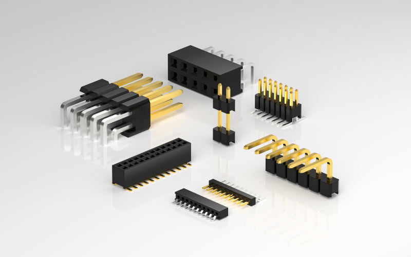
For applications requiring even greater mechanical resilience—such as vibration-prone or impact-heavy board-to-board connections—TXGA’s Round Hole Pin Header & Female Socket Connector uses a round needle and hole design that provides stronger support and impact resistance under vibration compared to standard flat pins. This connector is built with PPS heat-resistant resin (also UL94V-0 flame retardant rated), supports single row (2–40 pins) or double row (4–80 pins) configurations at 2.54mm or 2mm pitch, and operates reliably between -40ºC and +105ºC, with a maximum current of 3.00A per contact, maximum voltage of 60V, contact resistance of 20mΩ Max, insulation resistance of 1000MΩ Min, and withstand voltage of 100VAC r.m.s.
Matching Connector Type to the Application
Not every soldering scenario calls for the same header design. TXGA’s header and socket connector line includes several configurations built for different constraints:
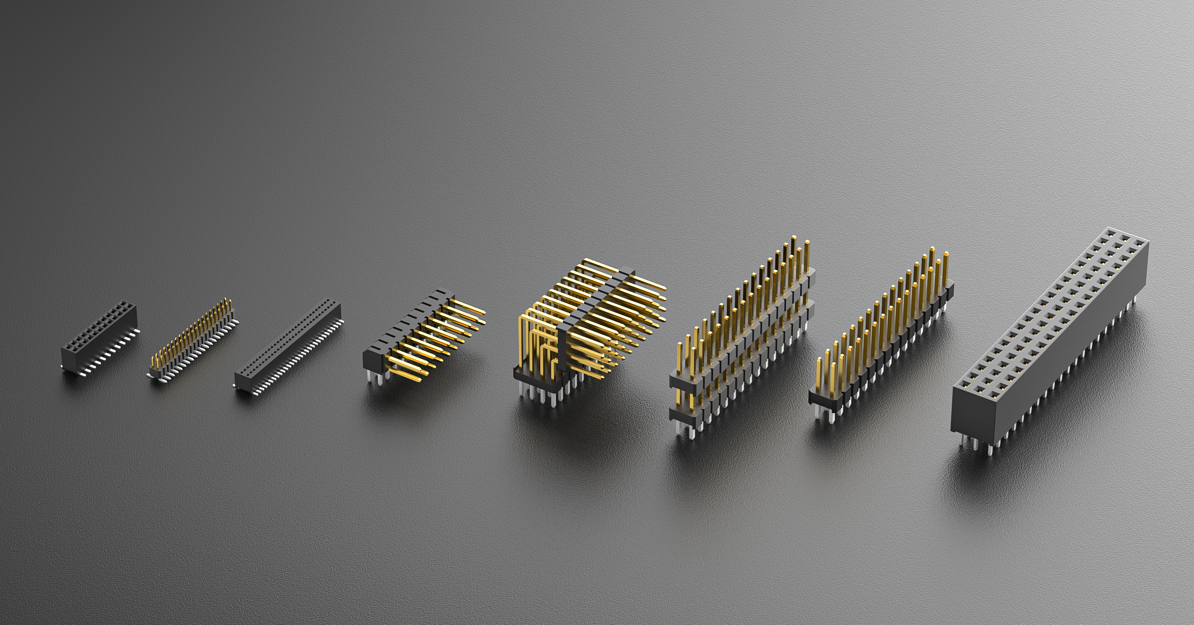
- Straight-through Pin Header & Female Socket: suited for standard board-to-board connections in space-constrained layouts, available in single, double, three, or four rows, with pitch options of 0.8mm, 1.0mm, 1.27mm, 2.0mm, and 2.54mm.
- Right Angle Header: designed for 90-degree side-entry mounting where vertical PCB space is limited, supporting lateral signal routing.
- Floating Header: incorporates built-in alignment play to absorb shock in high-vibration environments, reducing solder joint stress over the product’s operating life.
- Micro Pitch Header: offers reduced pin spacing for high-density routing in narrow, compact devices.
Selecting the correct header type before soldering—rather than adapting a mismatched connector to an unsuitable layout—reduces mechanical stress on solder joints and improves long-term reliability.
Validating Reliability After Soldering
Beyond soldering technique itself, connector quality assurance plays a direct role in joint longevity. TXGA applies multi-point quality testing, including insertion and extraction force testing and terminal retention force testing, to verify that soldered header connectors maintain stable mechanical and electrical performance after assembly. This testing approach reflects the company’s broader positioning as a connector supplier focused on technological innovation, quality-priority, and green production, with research and development investment exceeding 10% of annual sales, supported by a self-developed IFDMS system for company-wide digital management and an in-house digital design and manufacturing platform.
A Practical Case: Extreme Temperature Testing Environments
The importance of heat-resistant header materials is illustrated in a documented application involving a constant temperature and humidity test chamber used in laboratory and industrial verification fields such as pharmaceuticals, cosmetics, and food testing. This equipment simulates extreme climate environments—ranging from -40°C to +105°C—over long test cycles. TXGA’s PA6T heat-resistant nylon Pin Header was applied in this scenario, maintaining connection reliability across that full temperature range and achieving stable operation of internal circuit systems under the simulated extreme climate conditions.
Sourcing and Customization Considerations
For engineers and procurement teams sourcing header pin connectors, TXGA offers original factory direct sales with robust stock inventory, low minimum order quantities starting from a single piece, fast shipping, and independent mold customization services for specific environmental requirements such as extreme temperature, corrosion resistance, and high protection levels. This model, delivered through the TXGA Online Store, supports both small-batch prototyping and larger production runs without requiring separate sourcing relationships for standard and custom connector needs. Pre-sales selection assistance, customized solution development, and after-sales support including technical selection guidance and original factory engineering consultation round out the service model.
Conclusion
Soldering header pins successfully depends on more than technique alone—it requires selecting a connector engineered to withstand the thermal and mechanical demands of the intended application. By combining heat-resistant materials such as PA6T nylon and PPS resin, UL94V-0 flame retardant compliance, and documented multi-point quality testing, TXGA’s header and socket connector portfolio, built on nearly two decades of operations since its 2005 founding, addresses the specific failure modes that most commonly affect soldered joints in electronics, industrial, and testing equipment applications.
https://www.txga.com/m18clusters/pin-or-female-header.html
TXGA Connector