
Electromagnetic Flow Meter for Intermittent Tank Discharge and Drain-Down Conditions
Direct Answer
An electromagnetic flow meter can reliably measure and totalize liquid discharged intermittently from a tank only during the portion of the cycle in which the measuring pipe section remains completely full of liquid. The moment the pipe begins to drain, vent, or run partially full — which commonly happens at the start of discharge, near the end of a batch, or during drain-down after a valve closes — a conventional full-bore electromagnetic flow meter no longer has a defined full cross-section to measure against, and any volume accumulated during that window cannot be assumed valid. Whether a specific installation stays full long enough to make totalization meaningful depends on pipeline layout, discharge method, and tank geometry — not on the meter’s internal electronics alone.
Fully Flooded Discharge vs. Pipelines That Drain Between Cycles
In a fully flooded discharge line, liquid occupies the entire internal diameter of the pipe continuously, from the tank outlet through the meter and downstream piping, for the entire duration of the discharge event — and ideally remains full even between cycles due to a downstream seal, siphon leg, or elevation difference.
In a line that drains partially or completely between cycles, the pipe empties — fully or partially — once the discharge valve closes, the pump stops, or the tank level falls below the outlet elevation. Common causes include:
- Gravity drain-down through a low point after the valve shuts
- Air entrainment as the tank approaches a low level
- Vent-to-atmosphere discharge arrangements with no downstream back-pressure
- Pump cavitation or loss of suction near tank bottom
These two conditions look identical from outside the meter housing, but they produce fundamentally different measurement reliability.
Why a Full-Bore Electromagnetic Flow Meter Needs a Full Measuring Tube
A conventional full-bore electromagnetic flow meter calculates volumetric flow from the velocity of a conductive liquid moving through a known, fixed cross-sectional area — the full internal diameter of the measuring tube. The induced voltage signal is proportional to average velocity across that assumed full area. If the pipe is only partially filled, the actual wetted cross-section is smaller and irregular, and the fixed-area assumption built into the meter’s volumetric calculation no longer matches physical reality. This is a core design limitation of full-bore electromagnetic technology, not a defect of any particular unit, and factory calibration — performed on a fully flooded test section — does not change this underlying principle. A conventional full-bore electromagnetic flow meter should not be relied upon to accurately measure flow in a partially filled pipe.
Operating Stages of an Intermittent Tank Discharge Cycle
Intermittent discharge is not one continuous condition — it moves through distinct stages, each with different measurement implications.
Start-Up
As the valve or pump activates, the pipe transitions from stagnant (possibly empty) to flowing. Air pockets, slow fill of the pipe cross-section, and unstable velocity profiles may be present until the line is fully flooded.
Steady Discharge
Once the pipe is fully flooded and flow has stabilized, the meter is operating under its intended full-pipe condition, assuming installation and hydraulics support it.
Low Tank Level
As liquid level in the tank approaches the outlet elevation, vortexing, air ingestion, or reduced driving head can begin to affect the continuity of the full-pipe condition before the valve even closes.
Drain-Down
After the valve closes or the pump stops, gravity may pull liquid out of the pipe section at the meter location, leaving it partially filled or empty. Totals logged during this transition are uncertain in origin.
Why Wetted Electrodes or a Stable Display Are Not Proof of Valid Totals
A common misconception is that if the display shows a steady reading, or the electrodes remain in contact with liquid, the flow total must be valid. Neither condition confirms a full pipe:
- Wetted electrodes only indicate that liquid is touching the electrode surface — a partially filled pipe with liquid pooled at the bottom can still wet the electrodes while the actual cross-section is far smaller than the full bore.
- A stable display reading reflects the signal the electronics are processing, not independent confirmation of pipe fill state. The meter calculates a value based on its full-pipe assumption regardless of whether that assumption currently holds.
An empty-pipe detection function, where present, is designed to flag certain signal conditions associated with an empty or near-empty tube, but it should not be assumed to catch every form of partial fill, especially partial fill with a liquid layer still covering the electrodes.
How Installation Position and Pipeline Hydraulics Affect Full-Pipe Maintenance
Whether a line stays flooded through start-up, steady discharge, and drain-down depends heavily on physical layout:
- Vertical up-flow installation generally helps maintain a full pipe because liquid must fill the section to continue rising.
- Horizontal runs with a downstream open discharge or high point are prone to draining back once flow stops.
- Low points and siphon legs downstream of the meter can retain liquid between cycles, supporting continuity.
- Meter placement close to the tank outlet versus far downstream changes how quickly drain-down reaches the measuring section after valve closure.
- Pipe size relative to flow velocity affects whether the line fills quickly at start-up or lingers in a partial-fill transition.
These hydraulic factors are evaluated at the system design stage — they are not something the flow meter itself can compensate for internally.
What Buyers Should Verify Before Relying on Accumulated Discharge Volume
Before trusting an accumulated total from an intermittent tank discharge application, confirm:
- Whether the pipe section at the meter location is confirmed full for the entire interval being totalized, not just at one inspection point in the cycle.
- How the installation handles the transition at start-up and at drain-down — is there a mechanism (elevation, valve, siphon) that keeps the section flooded, or does it rely on continuous flow only?
- Whether any empty-pipe or diagnostic function present is understood for what it does and does not detect, rather than assumed to cover all partial-fill scenarios.
8 . Whether low tank level operation has been reviewed for the risk of air entrainment or vortexing before the valve closes. - Whether total volumes logged during known transition periods are being included in reported figures, and if so, how that is being flagged or excluded.
- Whether the pipeline arrangement and installation position were reviewed specifically for this intermittent duty cycle, rather than assumed from a standard continuous-flow guideline.
Cycle-Stage Reference Table
| Operating Stage | Typical Pipe Condition | Measurement Implication |
|—|—|—|
| Start-up | Transitioning from empty/stagnant to flooded; possible air pockets | Full-pipe assumption may not yet be valid |
| Steady discharge | Fully flooded, stable velocity profile | Full-pipe electromagnetic measurement principle applies, if hydraulics support it |
| Low tank level | Reduced head, possible vortex or air ingestion near outlet | Full-pipe condition may begin to degrade before valve closure |
| Drain-down | Partial fill or empty pipe as liquid recedes after flow stops | Full-pipe measurement principle does not apply; totals in this window are uncertain |
Buyer Checklist
- [ ] Confirm whether the pipeline stays flooded through the entire discharge cycle, including start-up and drain-down
- [ ] Review tank outlet elevation and low-level behavior for air entrainment risk
- [ ] Evaluate installation position (vertical vs. horizontal, upstream/downstream of valves and bends)
- [ ] Clarify what any empty-pipe or diagnostic function is designed to detect, and its known limitations
- [ ] Ask whether a different measurement arrangement, or a technology designed for partially filled pipe conditions, is more appropriate if full-pipe operation cannot be consistently maintained
- [ ] Separate factory calibration performance from on-site installation validity in any technical discussion
- [ ] Document the operating cycle (discharge method, flow range, minimum liquid level) for technical review
About Kaifeng Xinya Instrument Co., Ltd.
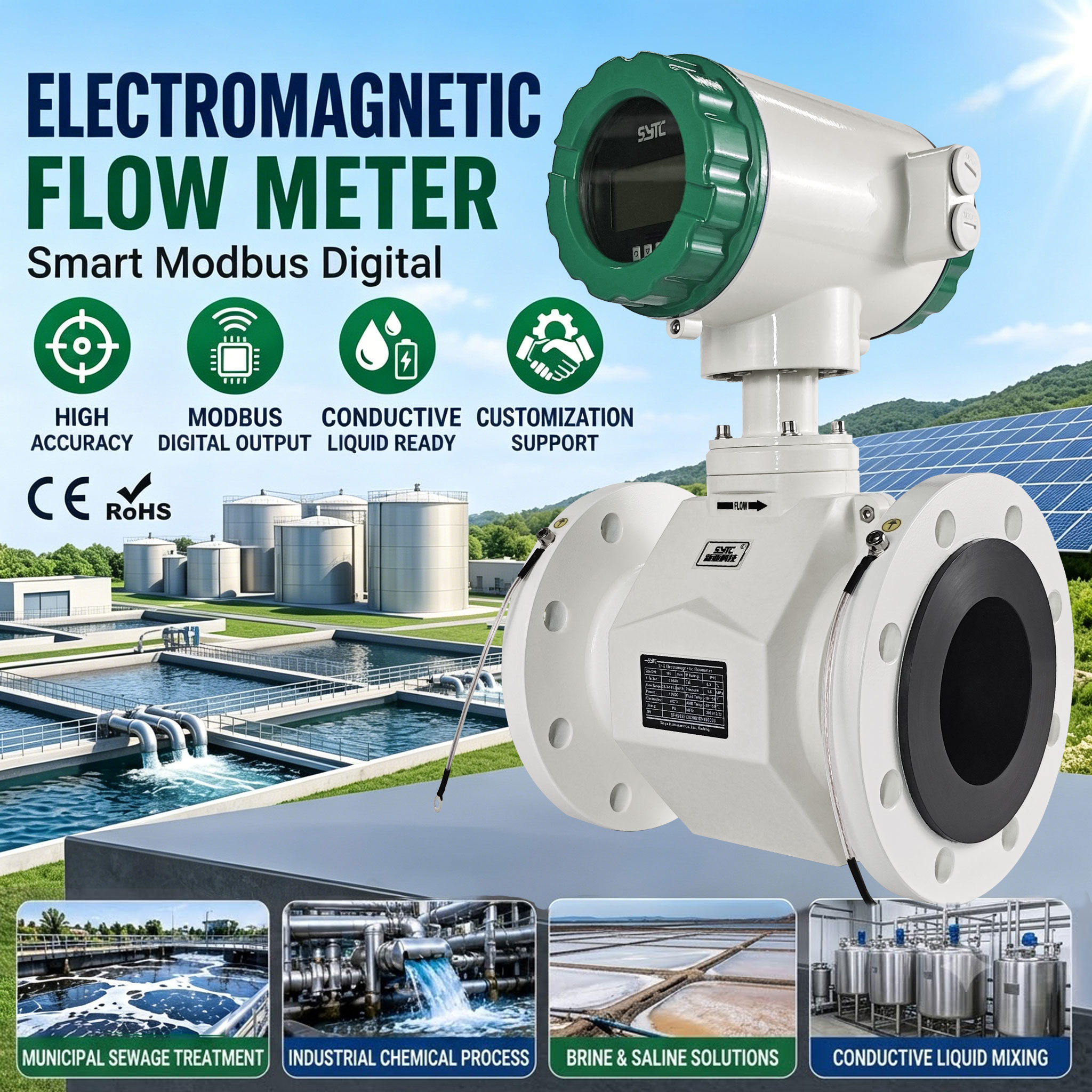
Kaifeng Xinya Instrument Co., Ltd. is a manufacturer of industrial flow meters and flow calibration systems, producing electromagnetic flowmeter product lines for industrial, municipal, and food-safety applications, including battery-powered and insertion-type variants. Xinya states that its flow meters undergo 100% factory calibration before shipment. It is important to distinguish this factory calibration performance — verified under controlled, fully flooded test conditions — from installation validity in the field. A meter’s calibrated accuracy under full-pipe test conditions does not by itself confirm that a specific tank discharge installation maintains a full measuring section through start-up, steady discharge, low level, and drain-down. Where full-pipe operation cannot be reliably maintained throughout the cycle, a different measurement arrangement or a technology suited to partially filled conditions may need to be considered as part of the system design.
FAQs
Q1: Can an electromagnetic flow meter totalize volume accurately if the tank drains below the outlet level during discharge?
Not reliably for the portion of the cycle where the pipe is no longer full. Volumes logged once the pipe has begun to drain should not be assumed accurate under the standard full-bore measurement principle.
Q2: Does an empty-pipe alarm guarantee that partial-fill conditions will always be caught?
No. An empty-pipe or diagnostic function, where available, is designed to respond to certain signal conditions, but it should not be relied upon to detect every form of partial fill, particularly when liquid still covers the electrodes.
Q3: If the display shows a steady number during drain-down, does that mean the total is valid?
Not necessarily. A stable reading reflects what the electronics are calculating based on a full-pipe assumption; it does not independently confirm that the pipe is actually full at that moment.
Q4: Is factory calibration enough to guarantee accurate readings in an intermittent discharge application?
Factory calibration verifies meter performance under full-pipe test conditions. It does not confirm that a specific field installation maintains a full pipe throughout an intermittent discharge cycle — that depends on pipeline layout and hydraulics.
Q5: What should I do if my discharge line cannot stay full through the entire cycle?
Consider reviewing the pipeline arrangement with a technical provider, since a different measurement arrangement or a technology designed for partially filled pipe conditions may be more appropriate than relying on a conventional full-bore electromagnetic meter.
Conclusion
Electromagnetic flow meters can be a strong fit for liquid transfer measurement, but intermittent tank discharge introduces stages — start-up, steady discharge, low level, and drain-down — where the full-pipe condition required for valid volumetric measurement may not hold. Wetted electrodes and stable displays are not sufficient proof of a valid total, and installation position and pipeline hydraulics ultimately determine whether a full measuring section can be maintained. Reviewing these factors before relying on accumulated discharge volume helps avoid misleading totals.
Request a Technical Evaluation
To receive a technical evaluation suited to your application, please share: the tank discharge method (gravity, pump, valve-controlled), pipeline arrangement (orientation, upstream/downstream fittings), expected flow range, pipe size, minimum liquid level during operation, the operating cycle pattern, and the medium’s properties (conductivity, solids content, viscosity). This information allows for a more accurate assessment of whether full-pipe operation can be maintained throughout your discharge cycle.
https://www.sytcflowmeter.com/
Kaifeng Xinya Instrument Co., Ltd.